 1
1


Banner Image Courtesy of Markforged
Every 3D printed object begins its life as digital data, and the format you choose can make all the difference in how smoothly your model moves from design to finished part. In this “3D Printing File Format Glossary Part One,” we’ll walk through ten of the most common 3D printing file formats: from the ever‑popular STL triangles of the earliest stereolithography days to the modern, metadata‑rich 3MF packages and even the machine‑readable G‑code instructions that actually drive the printer’s motions. Let's get started!
STL (STereoLithography)
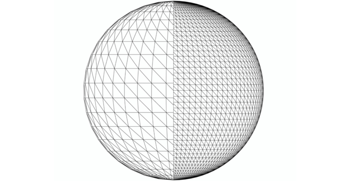
STL is one of the oldest and most common 3D printing file formats. Developed by 3D Systems in 1987 (inventor Chuck Hull), its name stands for Stereolithography (also called Standard Triangle Language). An STL file approximates a model’s surface with a mesh of triangles. It contains only geometric data – no color, texture, or material information – and assumes arbitrary units. STL supports both plain-text (ASCII) and compact binary forms, with binary being more common due to smaller file size. Because of its simplicity and wide support, STL is the de facto standard for 3D printing and rapid prototyping.
Geometry: Captures only surface geometry as triangular facets.
Attributes: No color, textures or metadata – surface only.
File Type: .stl extension; supports ASCII and binary encodings.
Usage: Universally supported by CAD and printing software; often required by 3D printing services.
Limitations: Large files for complex shapes; lacks scale/unit info and advanced features (color, assemblies, etc).
STEP (ISO 10303-21)
STEP (Standard for the Exchange of Product Model data) is an ISO-standard CAD exchange format (file extensions .stp/.step) dating from the 1990s. Unlike mesh formats, STEP is a rich, text-based (ASCII) format that describes precise 3D models – including solids, surfaces, curves, and assemblies. As an ISO 10303-21 standard, it retains full geometry and parametric data for high-precision engineering use. STEP files can include part hierarchy and metadata, making them ideal for complex part and assembly transfer between CAD systems. Because STEP preserves design intent and accuracy, it’s widely used in industry (aerospace, automotive, etc.), though most 3D printers first convert STEP to a mesh format before slicing.
Detail: Encodes exact CAD geometry (solids, surfaces, curves) and supports multi-part assemblies.
Format: Plain-text (ASCII) file (ISO 10303-21 clear text); machine-readable schema with lines of coded data.
Usage: Neutral CAD exchange for engineering/manufacturing; ensures interoperability across CAD software.
Attributes: Can include units, tolerances, product metadata, material assignments – far more than simple mesh.
File Type: .stp or .step; human-readable but large files.
OBJ (Wavefront)
OBJ is a simple, open-format geometry file originally created by Wavefront Technologies. It is plain text and represents 3D shapes with lists of vertices, texture coordinates, normals, and polygonal faces. Each face lists indices of its vertices (triangles or quads), defining the mesh connectivity. OBJ supports optional accompanying .mtl files for materials (colors, textures), but the OBJ itself contains no scene or unit information. Because it is straightforward and widely supported, OBJ is commonly used to exchange models (in graphics, CAD, and 3D printing workflows) as an alternative to STL, especially when texture mapping or more complex meshes are needed.
Contents: Vertex positions (x,y,z), texture UVs, normals, and face definitions (vertex index lists).
Format: ASCII text (.obj); human-readable lines starting with v, vt, vn, f, etc.
Materials: Can reference a .mtl file for material properties (color, texture maps), but does not embed materials itself.
Features: Supports polygons beyond triangles; retains vertex normals and UVs (for proper shading/texturing).
Usage: Common interchange format in graphics and printing; more flexible than STL, but still geometry-only (no animation or CAD metadata).
3MF (3D Manufacturing Format)
3MF is a modern, XML-based format created specifically for 3D printing by the 3MF Consortium (including Microsoft, HP, Autodesk, and others). It was released in 2015 as an open standard. A 3MF file (extension .3mf) is actually a ZIP package (Open Packaging Convention) containing XML definitions of model data. Unlike STL, 3MF can store rich information: full-color textures, multiple materials, lattice structures, and build platform details within a single file. It makes 3MF more complete and efficient for complex prints. The format is extensible and maintained by an industry consortium, and many CAD/slicer programs now support exporting to 3MF.
Features: Full color and texture support, multiple materials, custom printer settings, and even build plates or support structures can be embedded.
Format: XML schema packaged in a zipped container (.3mf).
Standard: Open, ISO-aligned specification (3MF Consortium); designed to succeed STL for additive manufacturing.
Advantages: Compact (zipped), avoids STL’s limitations; preserves color and geometry in one archive.
Adoption: Increasingly supported in 3D printing ecosystems; e.g., Microsoft’s Print 3D and many printers now read 3MF natively.
AMF (Additive Manufacturing File)
AMF is an ISO/ASTM standard (ISO 52915, 2011) for 3D printing data. It was developed as an XML-based successor to STL. AMF can describe shape, materials, and color natively. An AMF file (extension .amf) is XML (usually compressed in a ZIP) that allows multiple objects (“constellations”), each composed of triangular meshes, along with material and color assignments. Because it supports volumetric compositions, graded or multiple materials, and lattice infills, AMF overcomes many limitations of STL. However, it saw limited adoption, partly because newer 3MF filled the niche.
Elements: Can include multiple parts/objects, each with its own color and material properties.
Geometry: Like STL, uses triangles to define surfaces, but can optionally define curved triangles.
Attributes: Native support for color, material, and lattice structures (unlike STL).
Format: XML-based, typically zipped (but still uses .amf extension).
Usage: ISO standard for printing; envisaged for richer models, but largely supplanted by 3MF in practice.
PLY (Polygon File Format)
PLY is a simple format (often called Stanford PLY or Triangle Format) for storing 3D meshes and point clouds. It was created at Stanford in the 1990s for scanned data. A PLY file begins with an ASCII header describing the data layout (number of vertices, faces, and properties), followed by the data. It supports two encodings: plain ASCII or binary for compactness. At minimum, a PLY defines vertex coordinates and face indices (typically triangles). Unlike STL, PLY easily supports additional per-vertex attributes such as RGB color, normal vectors, transparency, etc. PLY is widely used in 3D scanning and research; it can store raw point clouds or meshes with per-vertex data for color or sensors.
Origin: Developed for 3D scanning (laser scan output), also called Stanford Triangle Format.
Structure: Header (+variant) declares elements (vertices, faces) and properties, followed by data. Two variants: ASCII or binary.
Attributes: Supports arbitrary per-vertex or per-face properties (e.g., color, normals) in the header.
Usage: Often used as an intermediate format in scanning and graphics; models can include vertex colors or point-cloud data.
Limitations: Less standardized in CAD pipelines; mostly for raw mesh/point data rather than refined CAD features.
VRML / X3D (Virtual Reality Modeling Language)
VRML is an older (circa 1995) format for interactive 3D scenes, and X3D is its modern successor. A VRML file (extension .wrl) describes a virtual “world” with geometry, appearance, lighting, and animation capabilities. Importantly for 3D printing, VRML can encode colors and textures on surfaces. In fact, printing services (e.g., Shapeways) often recommend VRML for full-color models, since STL cannot store colors. X3D (Extensible 3D) is an XML-based ISO standard that extends VRML (backward-compatible) with more features (advanced geometry types, shaders, etc.). Both VRML and X3D can represent rich color and material information, making them useful for multi-color printing and complex scene interchange.
VRML (.wrl): Textual scene graph format from SGI; supports 3D geometry with color, textures, and even animations. Often used for web/interactive 3D. Shapeways recommends VRML for color prints.
X3D (.x3d/.wrl): XML successor to VRML (ISO 19775) by Web3D Consortium. It encapsulates full 3D scenes (geometry, color, lighting, animation) and is more modular. X3D can be encoded in XML (.x3d) or classic VRML syntax (.wrl).
Color support: Both can encode per-vertex or per-shape color/materials and textures, enabling full-color prints.
Usage: Primarily for visualization and graphics; less common as direct printer input, but converters exist (collada→STL, etc.).
IGES (Initial Graphics Exchange Specification)
IGES (pronounced “I-ges”) is a very old CAD exchange format (ANSI standard from 1980). It is an ASCII text format designed for exchanging 2D and 3D engineering data among CAD systems. An IGES file can describe wireframe, freeform surfaces, B-rep solids, and engineering drawings. Because it is vendor-neutral, IGES was widely used in industries like aerospace and automotive for legacy data transfer. However, IGES does not natively support modern attributes like colors or textures (it predates color printing) and has largely been superseded by STEP and other formats.
Purpose: Vendor-neutral CAD interchange for product design data (from 1980s).
Geometry: Can include curves, surfaces, B-rep solids, NURBS, and 2D drawing entities.
Format: ASCII text with specific record structure. File extensions .igs or .iges.
Usage: Supported by most CAD software for import/export, especially in legacy workflows. Rare in direct 3D printing pipelines today (typically converted to modern formats).
COLLADA (COLLAborative Design Activity)
COLLADA (.dae) is an open XML schema for 3D asset exchange, developed by the Khronos Group (ISO/PAS 17506). Sony and others originally created it to allow digital assets (meshes, materials, shaders, skeletal animations) to be shared between graphics applications. A COLLADA file is an XML document that can represent detailed scene elements: polygon meshes, texture maps, lighting, physics attributes, and even skeletal animation. While COLLADA is widely used in game development and graphics, it can also carry color and material data, which 3D printers can use. In practice, COLLADA is less common in direct printing workflows, but tools exist to convert .dae models (with color/texture) into printable formats.
Type: XML-based interchange format (.dae) for 3D digital assets.
Contents: Can encode meshes, materials, textures, and even animations or physics in a scene graph.
Origin: Developed by Sony/Khronos for broad compatibility in graphics and CAD.
Usage: Popular in games and visualization pipelines; can store color textures (unlike STL), so used when colored models need to transfer between tools.
G-code
G-code is not a model format but the instruction language for 3D printers (and CNC machines). A G-code file contains lines of commands (e.g. “G1 X10 Y20 F1500”) telling the printer how to move its print head and extrude filament. Each command specifies a specific action – such as moving to a coordinate or setting extruder temperature – so the printer knows exactly how to lay down each layer. Slicer software generates G-code from a 3D model by slicing it into layers and outputting the motion commands for each layer. The printer’s firmware reads the G-code line by line to execute the print. In short, G-code is the “machine language” of the printer, translating a digital model into mechanical movements.
Nature: Plain-text CNC programming language. Commands begin with G or M (e.g., G0/G1 for moves, M104 to set temperature).
Content: Specifies coordinates, speeds, extrusion amounts, temperatures, etc. (e.g., “move here, extrude this much”).
Generation: Created by slicers (Converts STL/OBJ into layered print paths).
Usage: The printer reads a .gcode file as the recipe for printing; it contains no model geometry per se, only instructions derived from the model.
Customization: Advanced users can tweak G-code by hand to optimize prints (e.g., adjusting speeds or adding comments), though typically it’s auto-generated.
Sources: Authoritative references and documentation for each format are cited above. Each entry is summarized from standards and industry sources.


