 0
0


Banner Image Courtesy of Protolabs Network
Quick Overview
High quality scans and reliable mesh repair are the foundation for successful 3D printing, reverse engineering, AR content, and digital archiving. Here are some practical steps from preparing the object and choosing the right scanning method to turning raw point clouds into watertight meshes suitable for production. Follow these best practices to reduce rework, speed up downstream workflows, and improve the accuracy and usefulness of your models.
Good Scans and Clean Meshes
A good scan captures geometry and texture faithfully so that subsequent processes work predictably. Poor capture or rushed cleanup causes failed prints, bad fits in assemblies, incorrect measurements for inspection, and slow rendering for real time use. Clean meshes save time in CAD reverse engineering and reduce the need for manual retopology. In short, investing time in capture and repair up front reduces cost and frustration later.
3D Scanning Methods
Choose the scanning method that matches the part size, required accuracy, material, and budget.
Photogrammetry
Uses overlapping photos to reconstruct geometry. Strengths include low cost and good texture capture. It works best for textured, non-reflective surfaces and larger objects. Limitations include difficulty with featureless or reflective parts and lower precision compared with metrology devices.
Structured Light Scanning
Projects a known pattern and measures deformations to compute shape. It delivers higher accuracy than photogrammetry for small to medium objects and is relatively fast. It struggles with very shiny or transparent surfaces unless treated.
Laser Scanning
Includes handheld and tripod mounted devices. Laser scanners provide high accuracy and handle a wide range of materials and sizes. They are often used for engineering and inspection tasks. Handheld laser scanners may require steady operator technique to avoid noise.
CT and X Ray Scanning
Ideal for internal structures, dense metals, and complex internal cavities that are impossible to capture optically. These systems are costly and are typically used in medical, aerospace, and quality inspection contexts.
When deciding, consider accuracy requirements, surface properties, and whether internal geometry must be captured.
Pre-Capture Best Practices
Prepare both the object and the environment to maximize capture quality.
Surface Preparation
Matte sprays or temporary coating powders can make reflective or dark surfaces more scan friendly. Avoid thick coatings that alter critical dimensions. For very small features, use minimal coating and document any expected dimensional change.
Background and Lighting
Use a neutral background and consistent diffuse lighting to avoid strong shadows that confuse algorithms. In photogrammetry, avoid patterned backgrounds that could be mistaken for features.
Stabilize the Object
Use a turntable or secure mounts to keep the object steady. For handheld scanning, ensure the object is fixed so the scanner operator can move smoothly.
Calibration and Scale
Include scale bars, ruler, or calibration targets in the capture if absolute dimensions matter. Calibrate your scanner according to the manufacturer recommendations before each session.
Planning
Sketch scan paths, plan for overlap, and decide capture resolution before starting. Good planning avoids reshoots.
Capture Tips for Each Method
Photogrammetry
Use a consistent focal length and avoid extreme zoom. Shoot with aperture set to provide sufficient depth of field, keep ISO low to reduce noise, and use a tripod for tiny objects where possible. Capture 60 to 80 percent overlap between consecutive photos, and take multiple passes from higher and lower angles.
Structured Light and Handheld Scanners
Maintain the recommended standoff distance and move at a steady speed. Keep the scanner orthogonal to the surface when possible and ensure at least 30 percent overlap between passes. Temporarily mask out highly reflective areas or use matte spray when appropriate.
Laser Scanners
Adjust point density according to the feature size. Perform multiple passes from different orientations to eliminate shadowed areas. For long parts, break the scan into segments and register them during processing.
For Reflective or Transparent Materials
Use matte coating, chalk spray, or a removable powder to create a scan friendly surface. For thin or delicate parts, consider CT scanning if available.
From Raw Scans to Workable Meshes
A practical pipeline converts raw data to a usable polygon mesh.
• Import and organize: Keep raw data organized by session and orientation. Back up original scans before major processing.
• Registration and alignment: Align multiple scans using markers, targets, or feature based registration. Check alignment residuals and re-register if error exceeds acceptable tolerance.
• Noise removal and decimation: Remove outlier points and spikes. Decimate point clouds carefully to preserve important geometry while reducing file size. Avoid over decimation that destroys thin features.
• Meshing: Generate a mesh using best practice settings for smoothness and fidelity. Use adaptive meshing to keep polygons where needed and reduce them in flat areas.
• Export formats: Use PLY or OBJ to preserve vertex normals and texture. Use STL for final 3D printing when texture is not required.
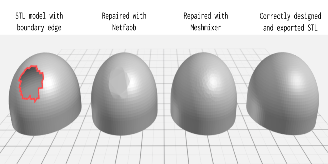
Mesh Repair Workflow
Follow a step-by-step repair flow to produce a watertight and manufacturable model.
• Inspect: Run automated checks to detect holes, non-manifold edges, inverted normals, and isolated islands. Visually inspect critical areas.
• Remove islands and spikes: Delete small disconnected components and floating noise. Smooth spikes and extraneous geometry.
• Fill holes: Use automatic hole filling for simple gaps and manual patching for complex or high detail regions. Ensure filled surfaces respect original geometry and do not introduce sharp artifacts.
• Fix normals and manifold issues: Recompute normals consistently and repair non manifold edges so the mesh becomes manifold and printable.
• Retopology and simplification: For CAD or animation use, retopologize to create cleaner quads and predictable edge flow. For real time or AR, create levels of detail and bake high resolution details to normal maps.
• Thickness and structural checks: For 3D printing, perform thickness analysis and ensure minimum wall thickness targets are met for the intended technology. Add internal supports or modify geometry where necessary.
• Validate: Run final checks for watertightness, correct orientation, and scale. If the model will be printed, slice a section to preview supports and detect potential print failures.
Optimization and Final Checks
Here are some tailor final steps to the target application:
• For 3D printing: Orient the part to minimize supports, check overhangs, and verify clearance and fit dimensions. Export in the slicer recommended file format and run a simulation.
• For CAD and engineering: Convert scanned surfaces to NURBS where high precision is required and ensure critical mating surfaces are reconstructed to nominal dimensions.
• For AR and real time: Create multiple LODs, bake textures and ambient occlusion into compact maps, and compress textures keeping visual fidelity.
• Final checklist: confirm scale and units, verify watertightness, run an interference or fit check when necessary, and keep a versioned backup of both raw scans and the repaired mesh.


