 0
0


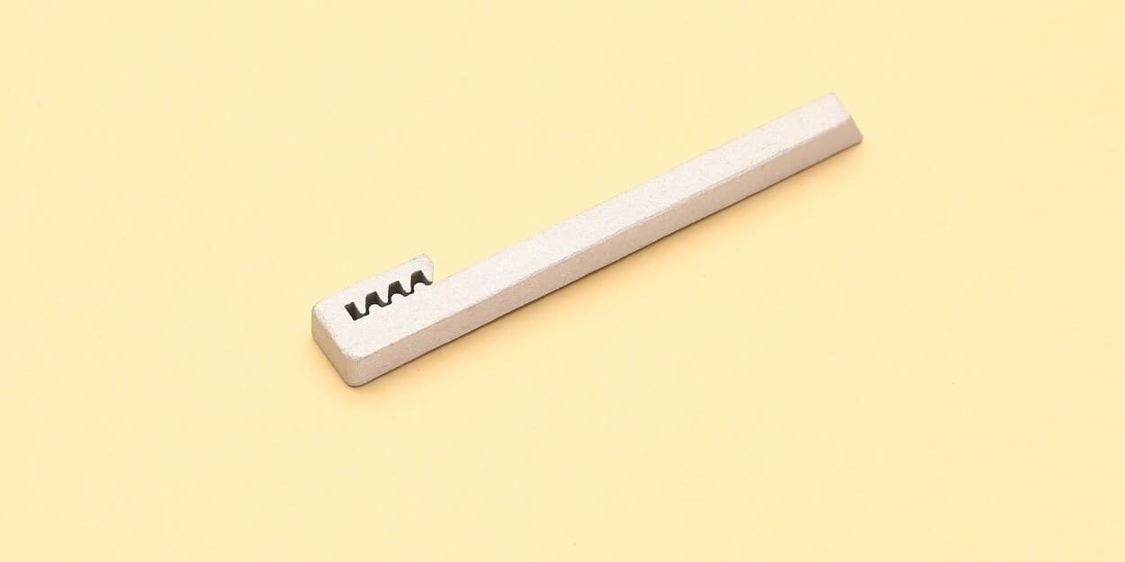
Banner Image Courtesy of Hi3DP
The Surface Finish of As-Printed SLM Metal
As-printed parts from Selective Laser Melting typically exhibit a rough surface texture and visible layer lines. Surface roughness values (Ra) often range from 10 to 25 µm, depending on machine settings and powder characteristics. The inherent roughness can affect fatigue strength, fit, and aesthetic appeal, making post-processing essential for many end-use applications.
Surface Roughness and Layer Lines
1. Ra values between 10 µm and 25 µm are common straight off the build plate.
2. Visible “stair-step” effect appears on sloped surfaces due to layer thickness (often 30–100 µm).
3. Surface shadows and micro-ridges form at the intersection of scan tracks, especially on down-skin areas.
Common Surface Defects
1. Balling: Molten metal pools solidify into spherical beads, leaving small protrusions.
2. Spatter: Particles of ejected powder fuse onto the part, creating nodules.
3. Unmelted Powder: Loose or partially melted powder adheres in valleys and crevices.
4. Keyhole Voids: Deep, narrow cavities from over-penetration of the laser beam.
5. Overhanging Features: Down-skin areas can sag or exhibit poor resolution without adequate supports.
What caused this surface quality?
1. Machine Parameters
The laser and scanning settings set the melt-pool behavior and track overlap, which define surface consistency.
Laser Power: Higher power deepens melt pools but can cause keyholing or excessive spatter.
Scan Speed: Faster scans reduce heat input, leading to poor fusion or balling; slower scans improve fusion at the cost of build time.
Hatch Spacing: Tight hatch overlaps smooth the surface but increase thermal buildup and distortion risks.
Scan Strategy: Rotating or alternating scan vectors minimize directional surface anisotropy.
2. Powder Properties
Powder characteristics determine how uniformly layers spread and how the laser couples energy into the material.
Particle Size Distribution: Narrow distributions (15–45 µm) pack densely for uniform melting.
Particle Morphology: Spherical powders flow better, reducing voids and irregularities.
Powder Purity: Oxides or moisture lead to porosity and inconsistent surface texture.
Flowability and Spreadability: Good flow ensures even layer deposition and fewer trap-ins of loose particles.
3. Build Orientation and Support Structures
How you orient parts dictates where overhangs occur and the nature of surface shadows.
Down-Skin vs. Up-Skin: Down-skin (overhang) areas tend to be rougher due to unsupported melt pools.
Angle of Inclination: Shallow angles (< 30°) exaggerate stair-stepping; vertical walls (90°) print sharper but still show scan tracks.
Support Placement: Dense supports improve heat dissipation but can leave marks when removed; strategic support removal zones preserve key surfaces.
4. Layer Thickness
Layer height is the simplest lever for resolution versus productivity.
Thick Layers (80–100 µm): Faster builds, more pronounced stair-step effect.
Thin Layers (20–40 µm): Smoother slopes and finer detail at the expense of longer print times.
Mechanical Post-Processing Techniques
You can rely on four main mechanical approaches to tame rough SLM surfaces: sandblasting, bead blasting, tumbling, and polishing. Each method uses abrasion or friction to smooth peaks, remove spatter, and blend layer lines, but they differ in equipment, speed, and the level of finesse they deliver.
1. Sandblasting
Sandblasting propels fine abrasive sand particles at high velocity against the part surface. It rapidly strips away loose powder and stress risers, making it ideal for heavy-duty cleaning and initial smoothing of robust components. Dust containment and proper respirators are essential when using this aggressive medium.
2. Bead Blasting
Bead blasting uses spherical glass beads instead of sand, yielding a more uniform, satin finish with minimal material removal. It’s perfect when you want to preserve fine details and avoid over-etching thin walls. A blast cabinet or enclosed nozzle system helps control overspray and captures beads for reuse.
3. Tumbling
Tumbling places parts and abrasive media together in a vibrating or rotating drum. Through continuous agitation, edges are deburred and surfaces are polished uniformly without hands-on sanding. It excels at batch processing, allowing hobbyists to finish multiple small parts evenly in a single cycle.
4. Polishing
Polishing refines a pre-smoothed surface to achieve shine or mirror-like reflectivity. It can be done by hand with polishing compounds and cloth wheels or mechanically with rotary tools and buffing pads. The process removes micro-scratches left by blasting or sanding and elevates the aesthetic appeal of metal prints.
Chemical and Electrochemical Methods
Acid etching, electropolishing, electrocoating, electroplating, and anodizing can refine SLM surfaces at the microscopic level.
1. Acid Etching
Acid etching immerses parts in a controlled acid bath that preferentially dissolves surface peaks, effectively “leveling” rough textures and deburring intricate geometries. It excels at cleaning stuck powder from tight crevices but demands careful ventilation and protective gear.
2. Electropolishing
Electropolishing submerges the metal part as the anode in an electrolytic cell. Under electric current, high-point asperities dissolve faster than low areas, producing a highly uniform, bright finish and enhanced corrosion resistance with minimal dimensional change.
3. Electrocoating
Electrocoating (e-coating) applies a thin, uniform polymer or paint layer using an electric field to deposit charged paint particles onto the metal surface. This method delivers consistent coverage—even inside holes and channels—while providing corrosion protection and a ready-to-paint primer.
4. Electroplating
Electroplating uses an electrolytic bath to deposit a thin metal layer (such as nickel, chrome, or copper) onto the SLM part. Beyond aesthetics, plated finishes improve wear resistance, electrical conductivity, and barrier properties against oxidation.
5. Anodizing
Anodizing converts the metal’s surface into a controlled oxide layer through an electrolytic process, most often applied to aluminum alloys used in SLM. It enhances hardness, wear resistance, and dye absorption for colored finishes, while maintaining the part’s dimensional accuracy.
Thermal and Surface Coating Options
Thermal and surface-coating treatments add functional layers or relieve stresses without the heavy abrasion of mechanical methods. These options can refine micro-roughness, improve durability, and introduce corrosion resistance or decorative effects: PVD/CVD thin films, powder or liquid paints, and anodizing.
1. Heat Treatment
Heat treatment uses controlled heating and cooling cycles to relieve residual stresses and refine the metal’s microstructure. While not a coating, it can slightly smooth microscopic peaks and valleys, improve dimensional stability, and prepare parts for downstream finishing.
2. PVD and CVD Thin-Film Coatings
Physical Vapor Deposition (PVD) and Chemical Vapor Deposition (CVD) both deposit nanometer-scale films onto metal surfaces. PVD sputters or evaporates metals or carbon compounds in a vacuum, while CVD decomposes gas-phase precursors on heated parts. Both yield hard, wear-resistant layers that conform to complex geometries.
3. Powder Coating and Liquid Painting
Powder coating and liquid painting apply polymer-based films over metal parts for protection and color. In powder coating, dry thermoset or thermoplastic powders are electrostatically sprayed and baked to form a durable film. Liquid painting involves primer and topcoat sprayed at lower temperatures, offering fine color control and specialty finishes.
4. Anodizing
Anodizing is an electrolytic process that grows a controlled oxide layer on aluminum alloys. It increases surface hardness, wear and corrosion resistance, and can be dyed to add lasting color. The layer is integral to the substrate and maintains tight dimensional tolerances.
5. Screen Printing
Screen printing forces inks or pastes through a mesh stencil onto the part surface, creating selective patterns or coatings. Hobbyists can use UV-curable or epoxy inks for graphics, or ceramic and metallic pastes for wear-resistant or conductive traces. It’s ideal for flat or gently curved faces where masking entire parts isn’t practical.
FAQs
Q: What’s the typical as-printed surface roughness (Ra) of SLM metal parts?
A: Between 10 µm and 25 µm.
Q: Which mechanical method should I start with for smoothing?
A: Sandblasting or glass-bead blasting are good choices.
Q: Can I achieve a mirror-like finish on SLM metal?
A: Yes—by combining very fine-grit polishing (1 000+), electropolishing, or diamond-like carbon (DLC) PVD coatings, you can push Ra down to sub-micron levels for true reflectivity.
Q: What’s the fastest way to batch-process multiple parts?
A: Tumbling.
Q: What build-orientation tips can improve as-printed finish?
A: Orient critical surfaces vertical or near-vertical (≥ 60°) to reduce stair-stepping. Minimize down-skin areas (< 30° overhangs) unless you can pack dense supports.


